Background
I was inspired to do this project when I watched a video where somebody used an airfoil database to build a big remote control plane. I thought it was interesting, and I realized that the properties he was using could potentially be determined using CFD. I decided to use ANSYS Fluent to try to replicate the lift and drag values for a NACA 4412 airfoil, based on a tutorial I was able to find online. The CFD that I had done before was somewhat basic, so I had become familiar with the software, but I had little practice refining meshes, analyzing results, or debugging errors. This project would give me an opportunity to check my work against verified sources, which turned out to be quite rewarding.
Target Values
NACA has experimental data available for their airfoils, so I was able to find lift and drag data easily for a range of Re values and attack angles, from NACA report 824. The NASA Langley Research Centre has a Turbulence Modeling Resource page where they used CFD to simulate the NACA 4412 airfoil, but I noticed the values were a bit higher than what was in the NACA publication. The NASA data was at 13.87 degrees, so I decided that I would test two angles: 0 degrees and 13.87 degrees. This way, I would have a few data points to compare, and I could which source was closer to my results. The NACA data was at 3 000 000 Re and the NASA data was at 1 500 000 Re, but I only tested at the higher Re, which was an inlet velocity of 43.9 m/s.
Methods
First, I used airfoiltools.com to generate a NACA 4412 plot with 200 points, and then I downloaded the coordinates to load into ANSYS for modelling. Following the tutorial, I used a 2D C-mesh with a height of 10 m and a length of 15 m, corresponding to 10 times the chord length of 1 m. I biased the mesh to ensure that the cells were very fine near the airfoil and behind it, but unfortunately ANSYS gave me some troubles that was causing the mesh generation to fail. The tutorial was using a different version of ANSYS, so I had to change some of my selections and adjust the bias factors for it to generate properly. I was still passing the Y+ check however to I determined that I could move on. I used a Spalart-Allmaras strain/vorticity-based model, with an inlet velocity of 43.9 m/s. Rather than changing the angle of the airfoil in between runs, I just change the direction of the inlet velocity, to save myself the remodeling time.
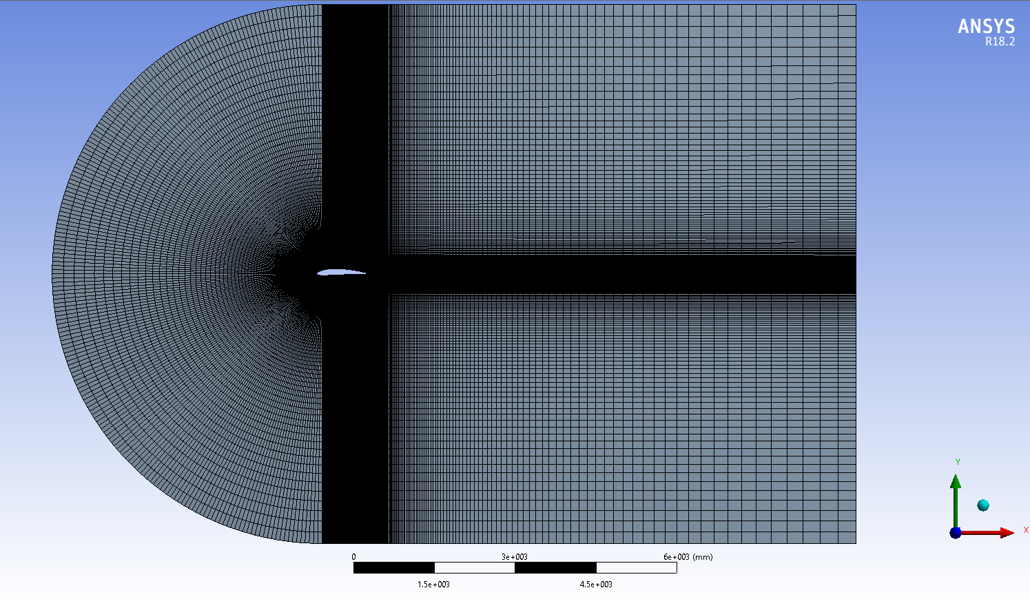
Figure 1: 2D C-mesh
Results
I found that my lift and drag results at 13.87 degrees were remarkably close to the NASA CFD results – within 4% (Table 1)! This meant that it was not too close to the NACA values, but it was still within a reasonable range (23%). At zero degrees, I was somewhat surprised to see that my lift results were very close, but my drag value was significantly over-predicting. There might be two reasons for this: the first is that I have a no slip wall condition on my airfoil that might be increasing drag, however this same condition produced a much more reasonable result at 13.87 degrees. The second possibility is the pressure spike at the leading edge of the airfoil at 0 degrees (Figure 2), that isn’t seen at 13.87 degrees (Figure 6). This concentration may be producing a rearwards force that significantly exceeds what would occur in real life.
Table 1: Summary of Results.
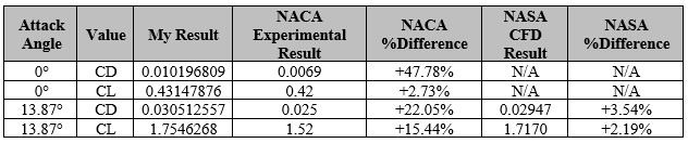
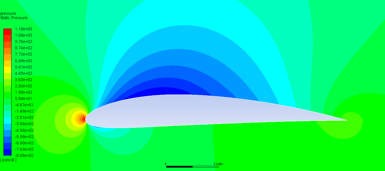
Figure 2: Pressure contour at 0 degrees.
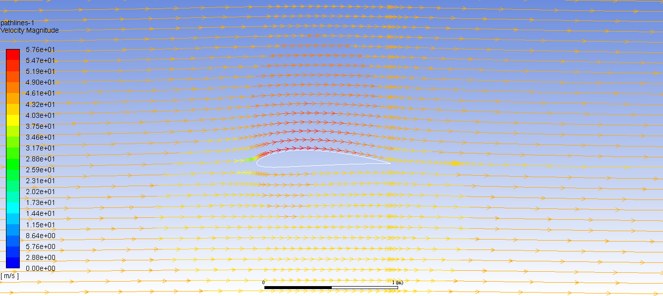
Figure 3: Streamlines at 0 degrees.

Figure 4: Close-up velocity contour at 0 degrees.
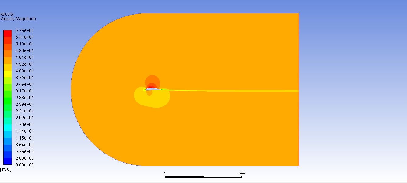
Figure 5: Far away velocity contour at 0 degrees.
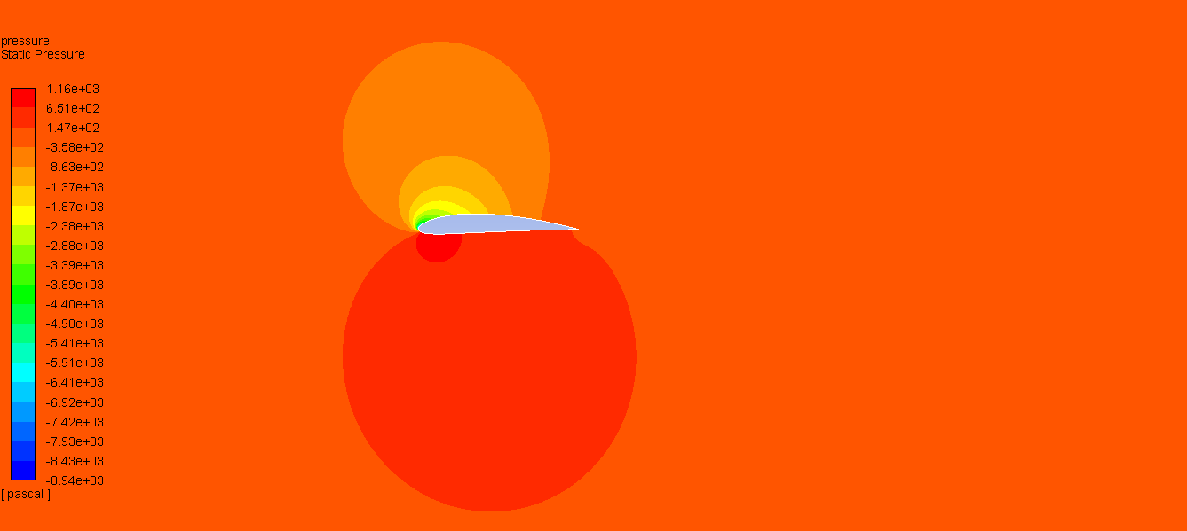
Figure 6: Pressure contour at 13.87 degrees.
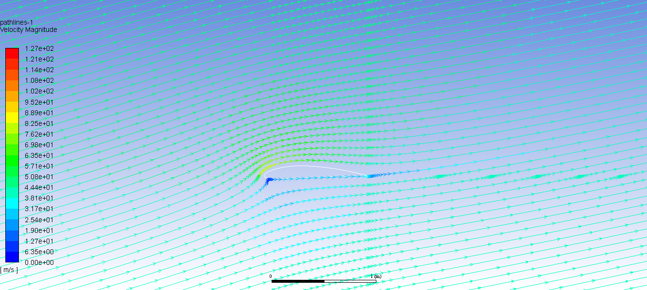
Figure 7: Streamlines at 13.87 degrees.
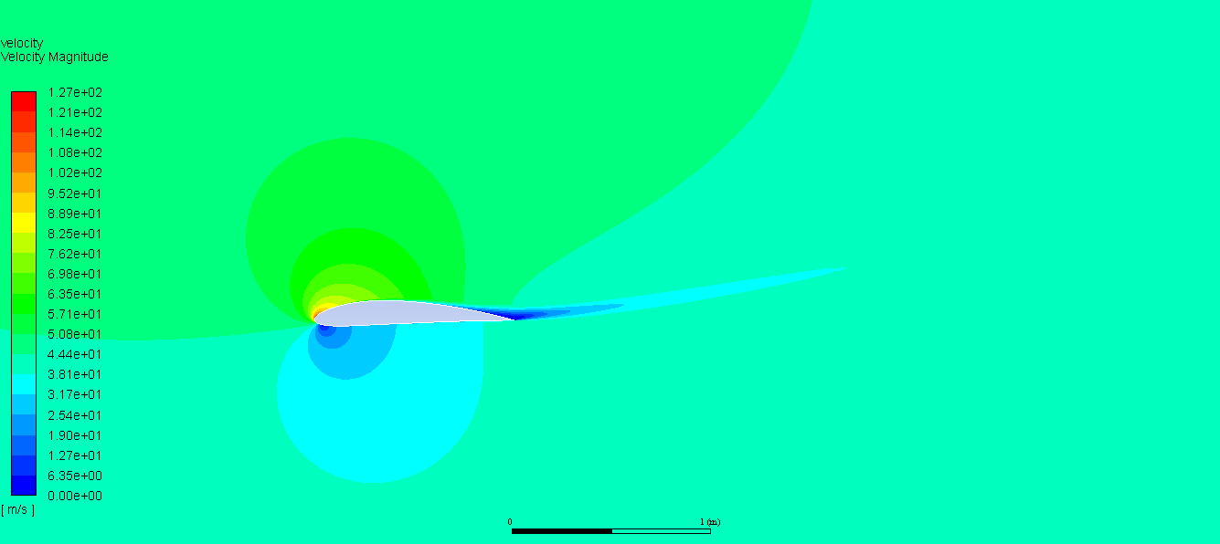
Figure 8: Velocity contour at 13.87 degrees.
Conclusion
Reflecting, this was a very interesting and fun project, and I was pleased at how close I was able to get to verified results. I was able to get much more familiar with the art/science combination of meshing, and my general knowledge of both airfoils and CFD improved significantly. My overall takeaway is an excitement for my first fluids class next semester!