Background
In 2022, one problem that the UWFM team encountered was that the tallest driver, a 99th percentile male, was too tall to fit properly in the vehicle. There is a rule that states that the angle of the shoulder harness with respect to the horizontal plane must not be over 10° above the plane. The driver sat comfortably if he sat without the harness on, but in order to meet this rule, he had to slide forward and slouch down to lower his shoulders. This caused a lot of problems for him, because in this position his feet would be too close to the pedals, meaning his knees fit awkwardly into the chassis. Because of this, it was decided that an ergonomics study for the 2023 vehicle should be done. An ergonomics study had been done the previous year (2022), and typically ergonomics studies are done every 2-3 years, which is why this was unusual.
Methodology
To do the study, a jig was constructed which mimicked sitting in the car, including a seat, back support, a steering wheel, and one pedal. All of these items were adjustable in terms of positioning and/or angle, so that each participant could find a combination that was comfortable for them. This jig was mostly the same as the one used in previous years, however due to the team losing some storage space from the school, some parts of the jig were misplaced and had to be remade.
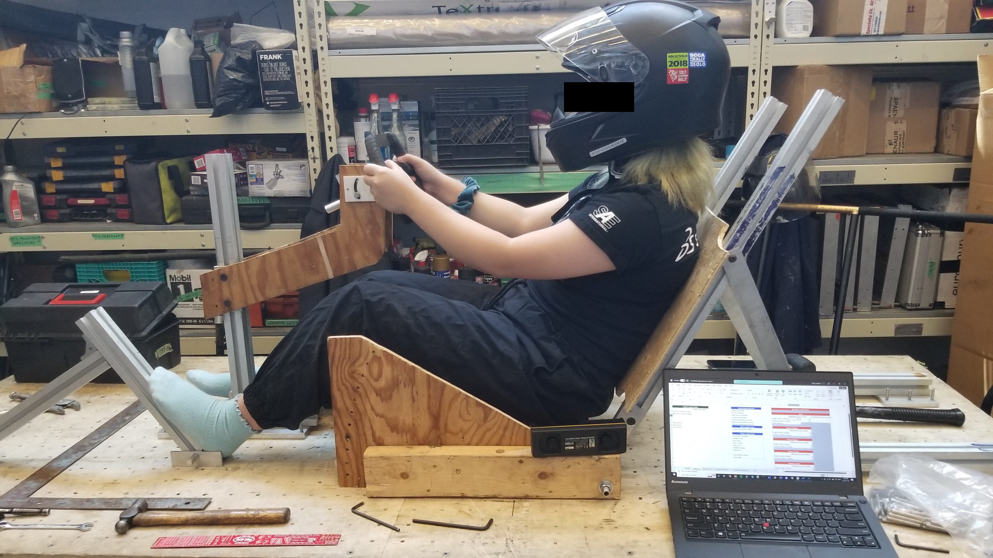
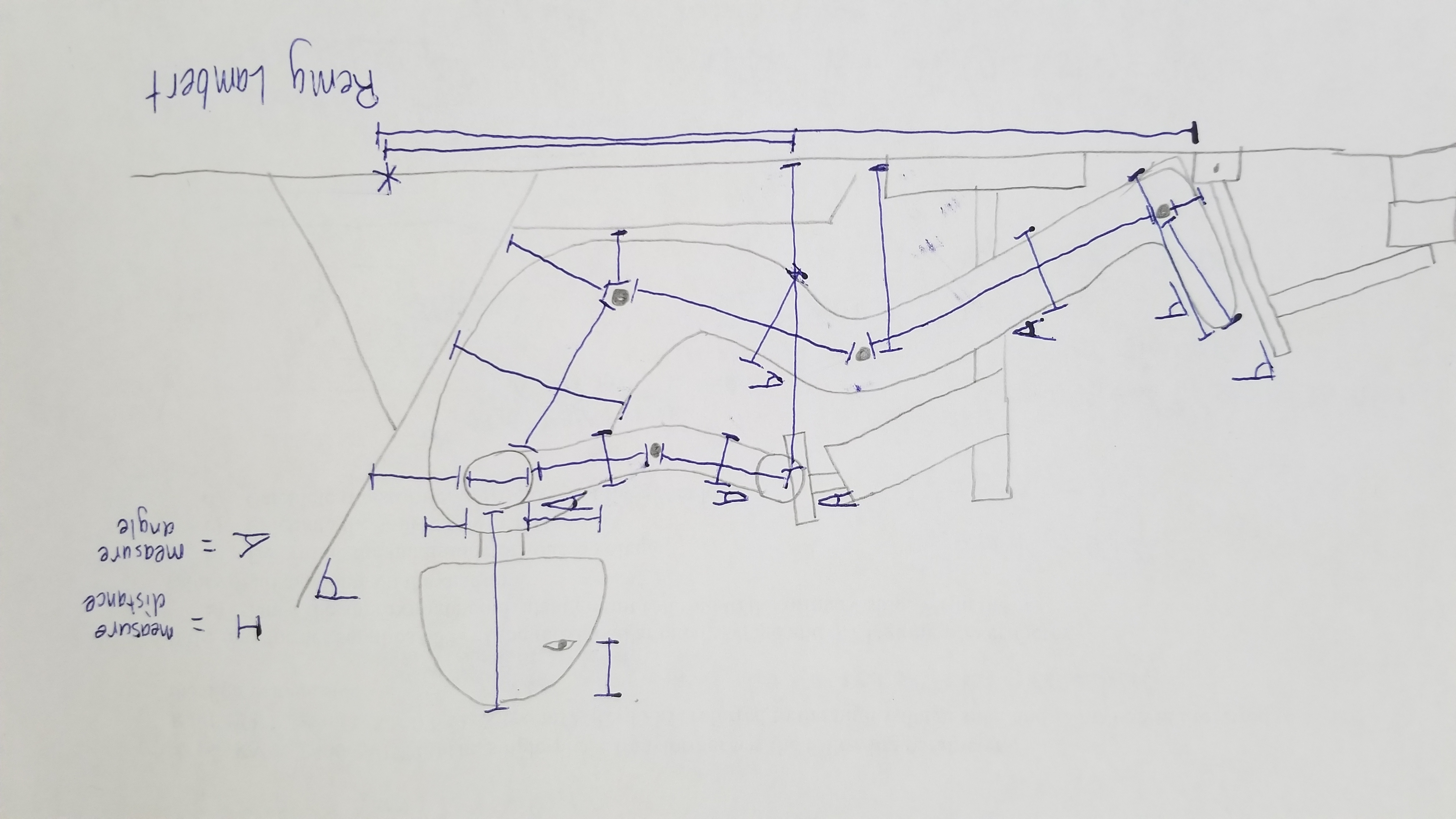
The study was conducted as such: the participant sat down in the jig, and then put on the helmet and seatbelt harness. The helmet changes the height of the participant, and the seatbelt harness has a buckle that the driver's hands can collide with when turning the steering wheel - this was a problem in the 2019 vehicle. Once the participant found their ideal position for steering wheel and pedals, body measurements (ex: knee to ankle length) would be taken so that the participant could be reconstructed in SolidWorks. After this, the steering wheel and pedal ideal positioning was recorded. Then, the steering wheel would be adjusted to the extreme viable locations in each direction: furthest highest, furthest lowest, closest lowest, and closest highest. These positions form a box that defines a range of steering wheel positions that are viable for each participant. This range was defined for three back angles: 50°, 55°, and 60° from horizontal.
Study
Six participants volunteered to be in the study: a 6th percentile female (team member), a 78th percentile female (team member), a 64th percentile male (driver), a 93rd percentile male (team member), a 97th percentile male (driver), and a 99th percentile male (driver). As you can probably tell, most of the participants were quite tall, including most of the drivers. Because of this, my study was biased to provide more comfort for larger people, but I deemed this acceptable because shorter people typically use a "booster seat" since all the drivers get custom seats, but larger drivers would not have this luxary if the car were made smaller. Also, Formula SAE rules state that the vehicle should be able to accomodate all people from 5th percentile female to 95th percentile male, but teams are allowed to tailor their vehicles to their drivers (with booster seats, adjustable pedals, adjustable steering wheel, etc.).
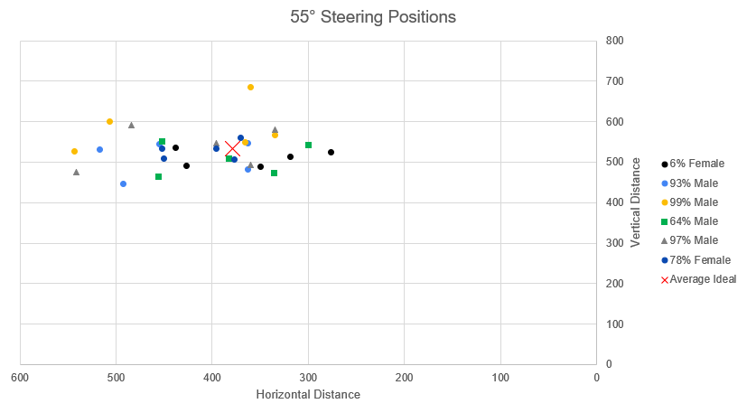
As can be seen in the graph, each partipant has five points, which represent their ideal position and the four corners that define their bounding box. Interestingly, several participant's have ideal positions that lie on the edge of or even outside of their bounding box! This is the case for the 6th percentile female as well as the 99th percentile male in the graph above, but at 50°, this occured for most of the participants. I believe that the reason for this is that the range of ideal positions is less of a bounding box, and more like a bounding oval. For example, with the closest lowest point, participants could usually go closer if they raised the steering wheel up a bit, or lower if they moved the steering wheel out a bit. This effect was less noticeable with the other corners however, which are typically bound more definitively by the sight line and arm length. During measurement, I just asked the participants to choose a somewhat central location for the closest lowest, but this point is probably not very representative of their true range.
All of the measurements that I took were in reference to a datum defined behind the driver. This position was thought to be the location of the origin in CAD, however there was an error and the positioning was offset horizontally when using data to define part locations in SolidWorks. To fix this issue, the driver's tailbone was set as the new datum, so by adding and subtracting offset values, CAD was able to be mated to the real life data. I was able to set all the CAD values pretty close to what I had chosen, except for the steering wheel angle which had to be increased to around 20° because the steering column U-joints were both past the recommended maximum angles.
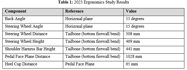
I noticed when analysing the data that last year's ergonomic hardpoints were close to the middle of viable locations for all the participants. This meant that I could shorten the chassis by 90 mm while still having everyone sit comfortably, which would reduce chassis mass by approximately 460 grams! I was worried that this might sacrifice a bit of comfort but I decided that it was worth it for the weight savings. After I chose the positioning and/or angle of each of the components, I set the jig up to match what I had chosen, so that team members were able to try out the jig. I found that everyone who sat in the jig (around 15 people total) was able to sit somewhat comfortably, which validated my choices and gave me confidence in the design.
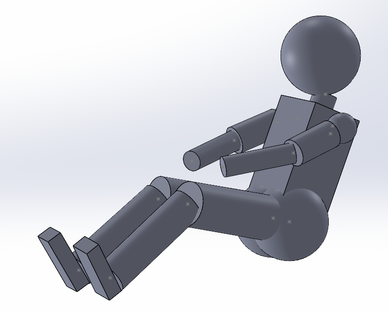
The final part of this project was to check for clearance issues in the CAD model. To do this, I used the body measurements that I took to create a 3D stick-figure as a SolidWorks assembly, which allowed me to place the model in the 2023 vehicle CAD and maneuver the limbs into position. The 99th percentile male and the 6th percentile female were the only models that I created, since they were the extreme cases. I was able to confirm that the pedals were in a position where the 6th percentile female could reach them, and the 99th percentile male's knees were not colliding with the chassis with his feet on the pedals. I did a similar check with the steering wheel and elbows. This is the model of the 99th percentile male:
Results
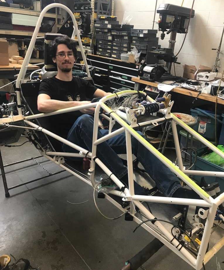
Sitting in the car 9 months later was very rewarding! The drivers have not noticed any particularily uncomfortable parts in the chassis, which means that I did my job well. Of course the car isn't extremely comfortable since there is no padding, but I was very happy that I was able to shorten the chassis so much with the drivers barely noticing.
Conclusion
This was the first major project that I took on for the UWFM team, and I enjoyed it as it was interesting to learn about ergonomics, and it had a large impact across several systems. For the vast majority of designs, human interaction will be a part of it in some way, so it's good to be familiar with basic ergonomic principles. On a personal note, this project introduced me to a lot of the team members, and I became more familiar with the team's PDM and file system. Plus, this project gave me a good excuse to be one the first people to sit in the car!