Background
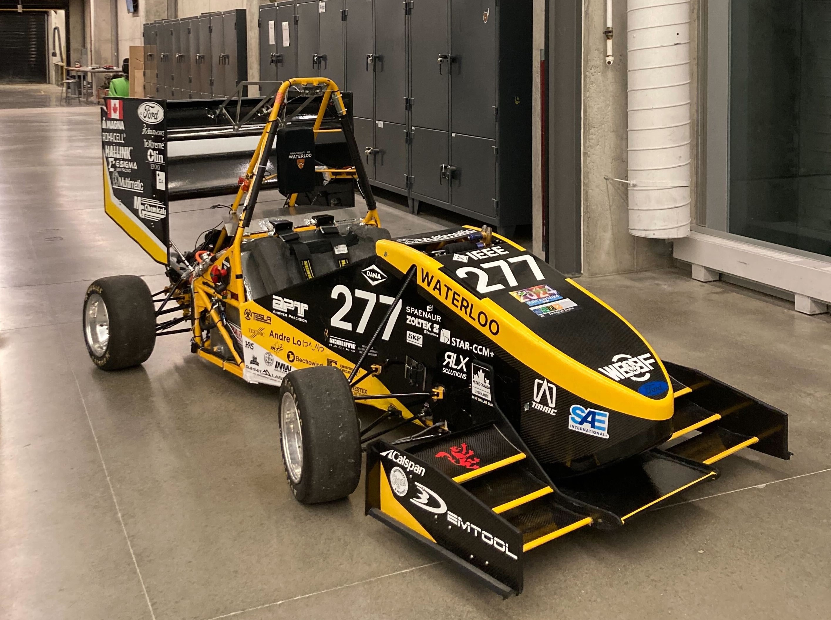
Prior to the 2024 season, two formula teams existed at UW: Waterloo Formula Electric (WFE), who competed in the electric formula competition, and University of Waterloo Formula Motorsports (UWFM), who competed in the combustion formula competition. As more and more schools were switching over to the electric competition, the Waterloo teams opted to combine into one, for increased resources and sponsorships, as well as combined knowledge and experiences from both teams. The new team was called University of Waterloo Formula Electric (UWFE). For the 2024 season, we opted to build a single motor electric vehicle to compete in the hybrid and electric competitions.
Since I had some analysis experience from my most recent co-op at BWXT, I decided to take on the Torsional Stiffness (TS) study for the new vehicle. Another student and I shared the role of chassis engineer, where he was focused on packaging and mounts, and I was focused on analysis. I worked on this project intermittently from July to September 2023.
Due to students graduating, covid, and a variety of other factors, it had been over 3 years since the team had done a proper torsional stiffness analysis on any vehicle. This meant that I had to mostly start from scratch, which was a bit challenging at the beginning. However, in the season prior, the frame designer was not able to attend competition, so I lead the chassis presentation. Because of this, I was able to talk with one of the judges afterwards and he gave me a lot of guidance on where to start with a TS study, as well as pit-falls to avoid. So with help from him and some formula alumni, I had a pretty good idea of how to set up my model for the best results.
Frame Design
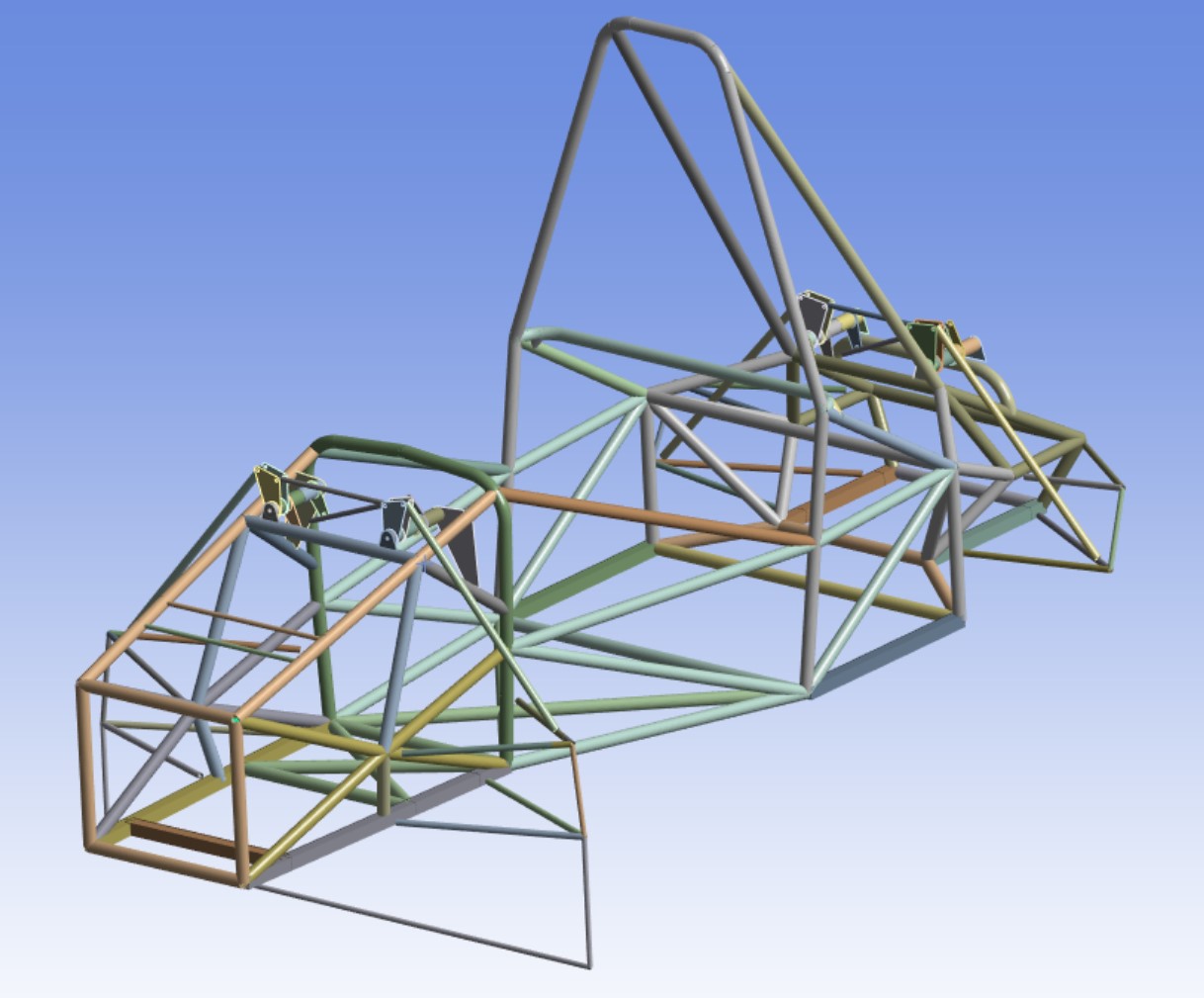
Instead of starting from scratch, we leveraged the old frame from UWFM since the roll-heave decoupled suspension design was being mostly carried-over into this vehicle. Most of the design changes happened at the rear to accommodate the battery and new motor, though the old differential was being reused as well. Packaging the accumulator was difficult, which ended up making the mid section much wider than in the past. After these big items had been packaged, changes were mostly made by myself to start improving the performance of the chassis, as well as some rule-related changes that we were required to make.
Targets
One huge help is that I did have a TS target: 1800 Nm/deg. This was determined by the team many years ago through a simple test. After the season had ended, they took the car out to the test track and tuned the suspension based on the driver feedback. After this, they cut one of the tubes to reduce the TS, and retuned the vehicle. They cut out tubes until the car was not stiff enough, and then measured the TS of the chopped chassis. They took this measurement by fixing the rear hubs, and connecting the front two hubs by a solid bar. They put offset weights onto the bar to induce a moment, and measured the deflection of the chassis to calculate the TS. By adding a safety factor onto this value, they determined that no vehicle should have less than 1800 Nm/deg. In the simulation however, I tried to get the stiffness above 2200 Nm/deg. This was based on a recommendation from the judge I spoke to, who advised me that beam simulations often overpredict the stiffness of the chassis.
Obviously, the best vehicle TS would come from a solid block of steel, however this would be very poor for mass. Having a stiffness target is a huge help in design, so that I know when to stop adding mass in favour of stiffness. I also tracked the stiffness per unit mass, or Nm/deg/kg, as a way to decide whether some stiffness was worth the additional mass.
Setting up the TS Study
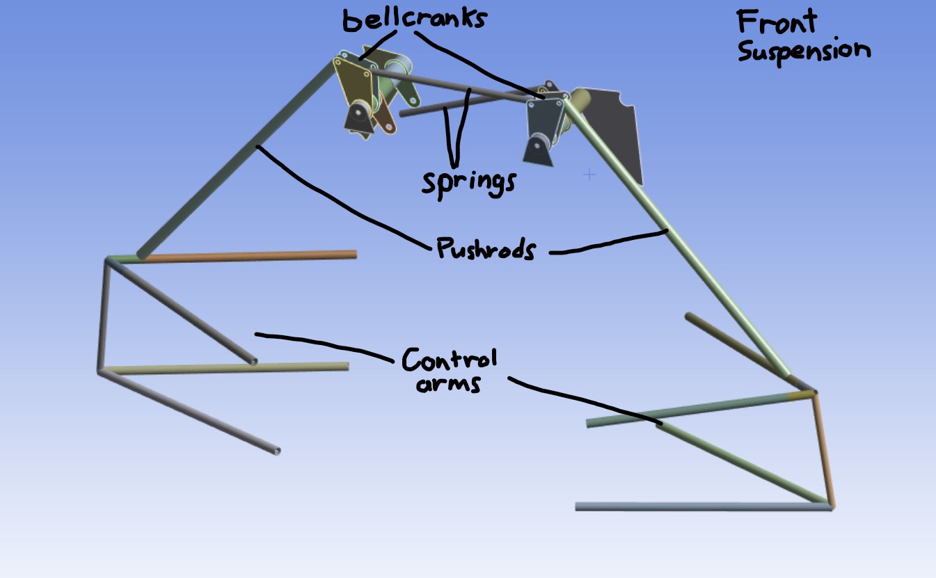
I used Ansys workbench to conduct the study since this is what I was familiar with from my previous co-op. Since the frame is almost entirely made of tubes, I primarily used beam elements, however I also used some shell elements to create some of the mounts and the bellcranks. The chassis was designed using 3D line sketches in SolidWorks, so I imported these sketches into Ansys for meshing. To ensure that the loads were applied accurately to the chassis, I fully modelled the suspension system, using rigid elements only in place of the springs. We use a roll-heave decoupled suspension system, which means that one spring is resisting vehicle roll, while the other resists heave, as opposed to a traditional setup where both springs control a portion of both movements. This system allows for much better tuning, but comes at the cost of increased mass due to the required bellcranks and pushrods. In our system, the springs are mounted on the top of the vehicle.
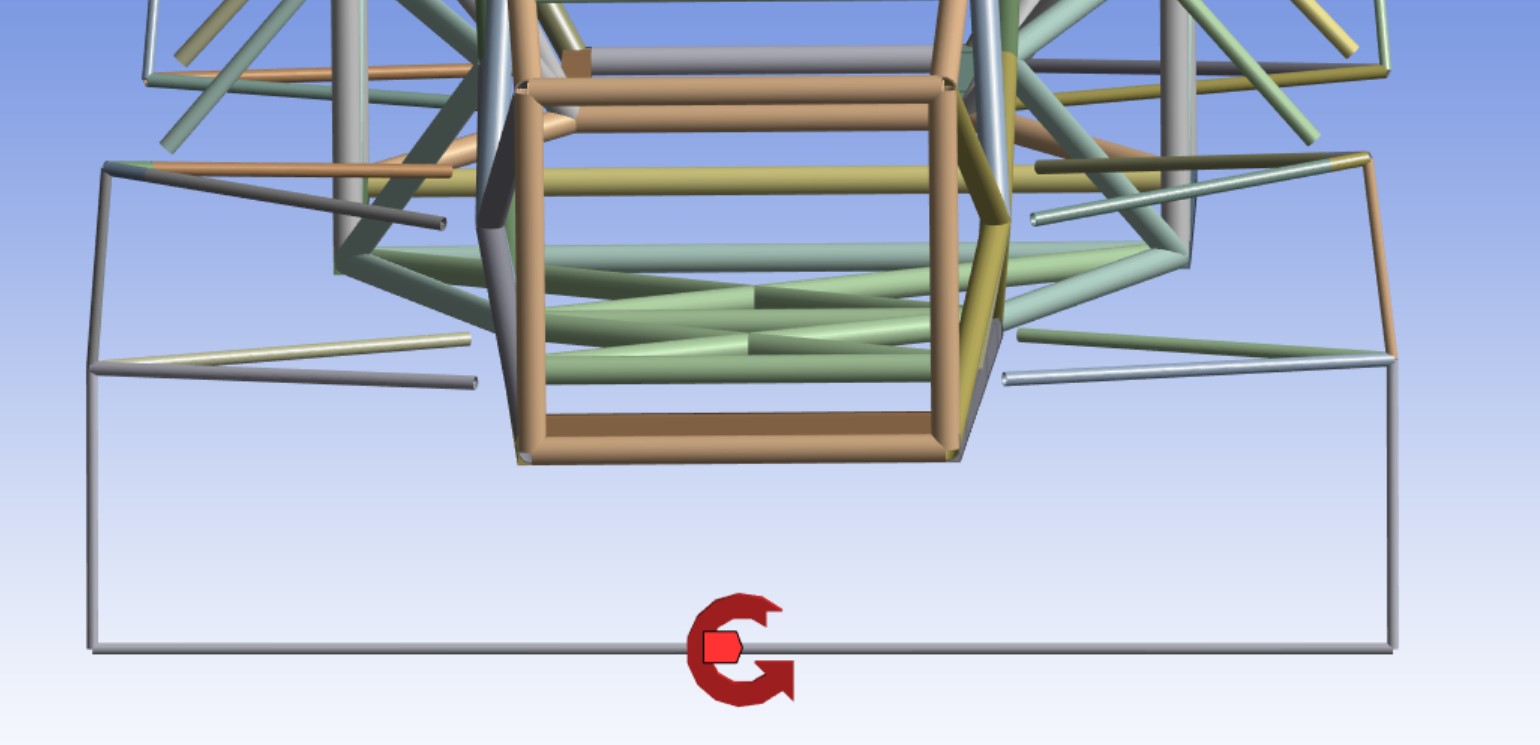
To apply the torque on the chassis, I connected the two front hubs with a rigid beam underneath the vehicle, and I applied a moment to this feature. This ensures that there are no bending forces on the chassis, and the load is applied evenly to both wheels so that the frame rotates about its natural center.
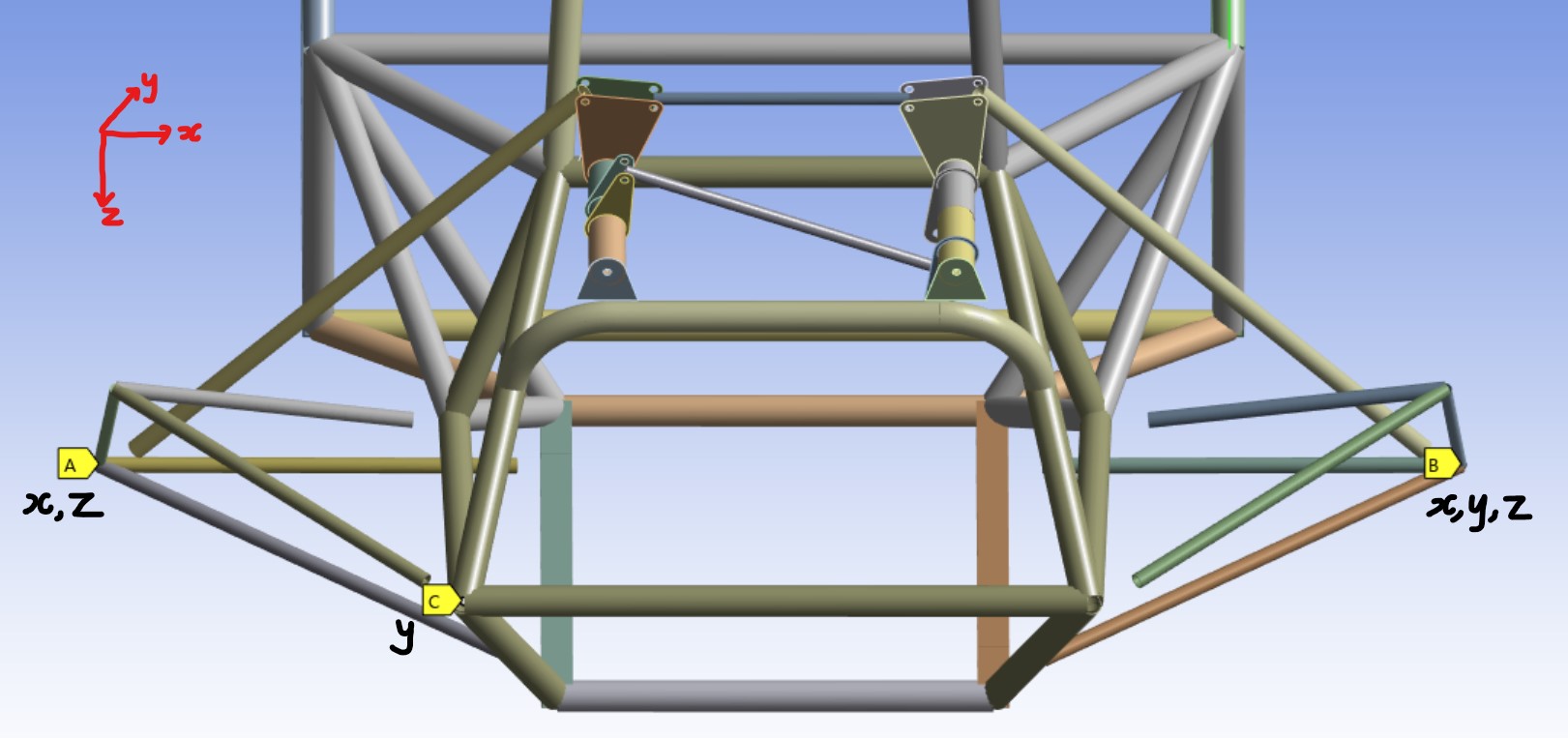
For the boundary conditions, I only used 6 constraints (1 per DOF) on the chassis so that the stiffness would not be artificially high due to overconstraints. To do this, I fixed x,y,z displacement on the rear right hub, x and z displacement on the rear left hub, and y displacement on a random elevated point to prevent rotation about the rear axle. The reason that a random elevated point is sufficient, is because there are no forces applied to the model that would cause heave rotation; the last constraint is only there to stabilize the solution by preventing random rotation. In the results, there is evidence for this since there are no elevated stresses around the point chosen.
One thing that I wasn't sure about was whether I should model the accumulator (battery). In past studies, the engine had been modelled as a solid block since it is so stiff, but the accumulator is a much larger piece with thin walls but a dense inside structure. I decided that I would conduct a test on last year's accumulator to determine the torsional stiffness, so that I could add a solid element to my model with the correct properties. I did it quite similar to how the frame stiffness was studied in the past: I fixed the rear ends of the box, and used offset weights to apply a torque. I determined that the stiffness was very low: less than 200 Nm/deg. After learning this, I decided not to include it in my model since it likely would not make any significant changes.
Analysis
To improve my understanding of the model, I used probes at multiple points along the chassis so that I could compare the stiffness of each section individually. However, TS is not a good way to compare structures with different lengths, since bars with the same stiffness will twist more or less depending on the length, thus making TS length dependant. A better way is to use a "twist modulus", which is based on the angle of twist formula, and is a combination of J and G which forms a length independent stiffness:
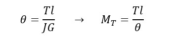
Where T is the torque, theta is the angle of twist, l is the length, G is the shear modulus, J is the polar moment of inertia, and MT is the twist modulus. Using this metric, I was able to determine that the rear was the least stiff section of the chassis, so I focused my efforts mainly on this area.
I calculated these values, along with the overall torsional stiffness, in an excel sheet which allowed me to track the improvements or decline with every change I made. I also used tube forces and moments to determine which tubes were having the greatest impact, and focused on thickening these while thinning tubes that were carrying smaller loads. Initially, I was studying larger changes such as tube node placements, however as the frame design become more and more locked due to mounting, rules, and ergonomic requirements, I focused on adjusting tube thicknesses to get improvements in TS/kg.
Results
When the project was finally done, I had achieved a final TS of 2295 Nm/deg, a mass of 35.1 kg, and a TS/kg of 65.31 Nm/deg/kg. From the initial design, the mass only went up 21.5%, but the TS improved by 53.8%!
Unfortunately, I never got a chance to measure the torsional stiffness of the chassis, since I left the team before the season ended when I headed off to Tesla in California. However, I was told that the stiffness of the vehicle felt good for the drivers and the suspension tuners, and the vehicle passed tech inspection at competition. Also, the team placed 4th in design finals for the 2024 hybrid competition!
Reflection
I really wish that I had been able to do a physical measurement of TS to validate my simulation, but despite that I am really happy with how this project went. I was able to use my Ansys and design knowledge to work on a really cool project, and I got great results in the end. I improved my simulation skills further, and this project helped me to get a simulation job at BRP, where I was eventually working on TS studies for real ATVs and SSVs! And luckily I was able to transfer the model and some of my learnings to the next chassis designer, so hopefully I had a positive impact on many teams to come!