Background
For a while now I have been interested in creating a generator that would allow me to charge my cell phone using my own muscle power. My first attempt was made out of Meccano, and used a crank connected to a high to low ratio pulley to spin the shaft of a small Meccano motor. I was able to make enough voltage to power an LED, but not enough to charge my phone. I created a second version out of Lego using pedals instead of a crank, with a higher ratio and using the same motor, but again I couldn't power anything more than an LED. I tried increasing the ratio on that version, but at that point it was impossible to turn the motor. You can see this old version working here. To charge via USB, the standard for most devices is 5V at 0.5A, but using the Meccano motor, I never measured more than 3.5V. So, I decided that it was time to go for something bigger.
Design Iterations
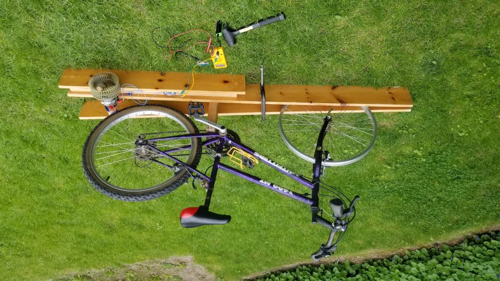
When I thought of using a bike as a crank, it seemed to fit the problem well in several different ways: it has already been designed ergonomically, it wouldn't have as much friction, the gears would allow me to have a higher end ratio because I could start with a low ratio, and I had access to a bike that wasn't being used! Because I was using a much larger crank, I needed a larger motor, so I used a 12V car blower motor. The motor already had a circular fan on the shaft so that is what I used to contact the bike tire. In the first design I mounted the motor on the top of the rear wheel using the rack so that I could ride while charging, but it was flimsy so it didn't handle bumps very well. After that, I decided to mount the motor on the bottom, and put the bike in a stationary frame instead. Also, the front tire was taken for use on another bike, so riding it was not really an option anymore.
Mounting the bike in a frame proved to be pretty successful, and I got my first measurement! Unfortunately, it was only putting out about 3.5V at maximum speed, the same as the smaller motor. Luckily, it was pretty easy to turn the pedals so I knew I could increase the ratio a fair bit. The plastic fan piece was just press fit onto the shaft, so I was able to remove it by heating it and using two pry bars against one another for leverage to slide the fan off. Once it was off, I tried to find a way to mount a skateboard wheel, but unfortunately I could not find a way to stop it from spinning freely on the shaft, since the shaft had no key or anything that I could use to fix the rotation of the wheel. Instead, I used a hole saw to create a wheel out of wood approximately the same size as the skateboard wheel, and drilled the center hole slightly smaller than the shaft all the way through. After widening one end of the hole slightly so that the shaft could go in part way, I used a rubber mallet to press fit the wheel onto the shaft. This worked well, and when I measured again, I was able to provide 6V!
After testing the new design with an LED, which worked, I got a bit ahead of myself and tried to charge a portable phone battery. I saw the light flash a few times (indicating that it was charging), and then it stopped suddenly. No sound, no puff of smoke, but when I tried to charge it by plugging it into the wall, the lights did not come on and the battery got very hot. OOPS... I can't be sure what killed it but I guess it couldn't handle much more than 5V. After that, I did some research, and I purchased a boost voltage converter, which takes a varying voltage and boosts it to a fixed amount at a lower current. Using this, as long as I stayed between 3 and 5 volts, it outputted a steady 5V! After testing it again with an LED, I was ready to put another portable charger on the line, and this time, it worked! I was happy to see that the lights started flashing, and they did not even falter until I ceased pedaling. It's probably the least efficient charging method ever, but it felt good to finally get a working and stable charge, after so many failures learning opportunities.
Components
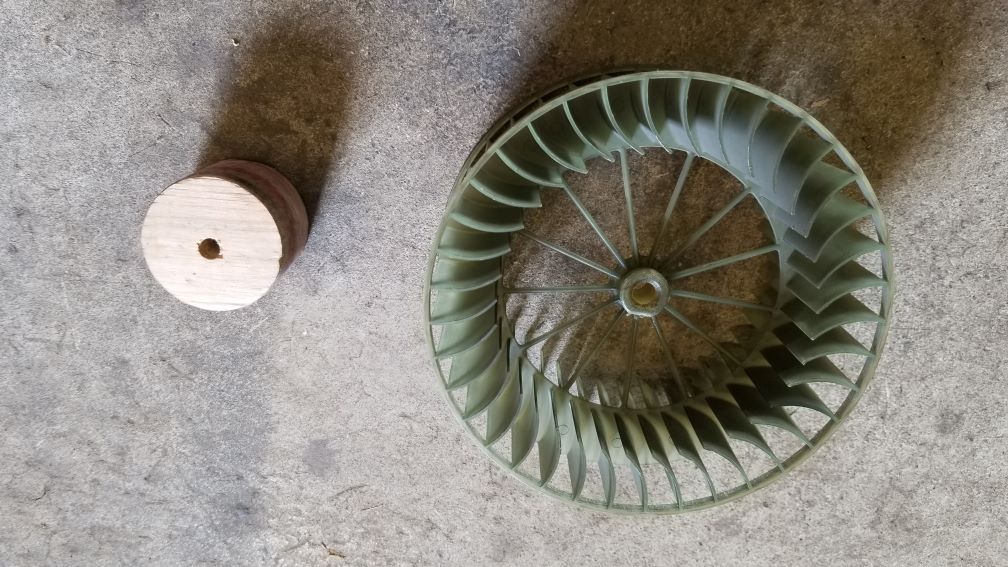
Here is the fan that came pressed onto the shaft of the blower motor on the left, and the wheel that I fabricated on the right. Because the radius of the wheel is much smaller, the ratio between the bike's rear wheel and it is larger. A larger ratio means that the shaft spins at higher speeds, but it is harder for me to pedal. However, this isn't an issue because I can start pedaling in the bike's lowest gear, and then shift upwards to get more speed if I need it.
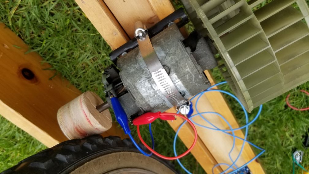
This is the blower motor itself, mounted in the final frame using gear clamps. As you can see there are actually two fans, one on each side, as the shaft goes straight through the motor. I only took off one fan to mount the wheel that I created, meaning that the other fan was still there creating air resistance. However, it was very difficult getting the other fan off, so I didn't want to go through that process again, and it didn't create a noticeable amount of drag.
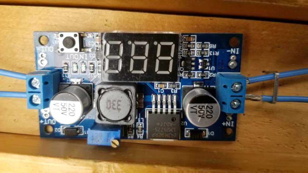
This is the boost voltage converter board. It takes a varying voltage between 3 and 34V and boosts it to anywhere between 4 and 35V. The important part is that the output must be greater than or equal to the input, meaning to get a stable 5V output, I needed to keep the input between 3 and 5V. The other option I was considering for this project was a buck converter, which does the opposite of a boost converter: it takes a high voltage and brings it down to a fixed amount. However, as the bike could only produce 6V and I needed 5V, it was a better idea to go with the boost converter. At first it seems impossible that this board can increase the voltage with seemingly nothing, but the way it actually does this is by lowering the current from the input to the output. Since power is voltage multiplied by current, energy is conserved when the voltage rises so long as the current drops proportionally. Having a lower current at the output means that theoretically, it should be more difficult for me to pedal because the input will need to be higher, and that current will create electric fields that oppose the motion of the blower motor shaft, but the load drew so little current that the effect was negligible. The 7-segment display that you see in the picture was a bonus volt-meter that could measure both the input and the output voltage. This was useful when setting the output voltage, because you do so by turning a screw in the potentiometer, which gives no indication itself of the output voltage. I bought the board on Amazon for about $20 here.
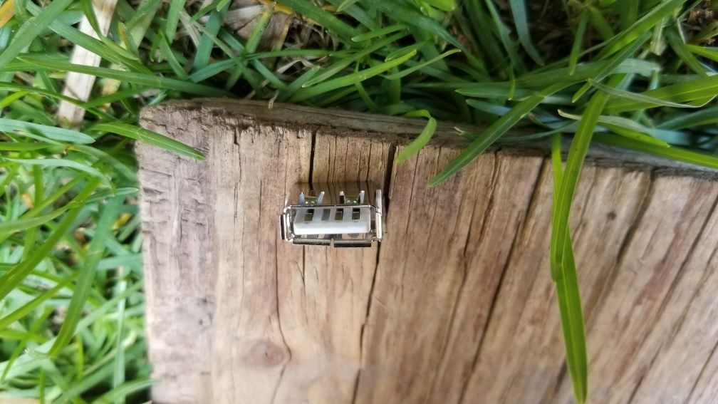
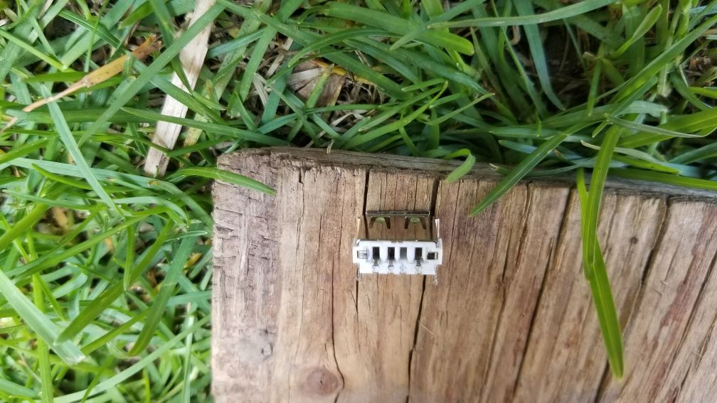
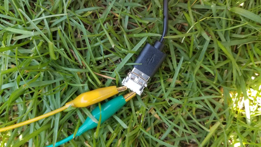
This is the USB port that I was using to interface with the phone charger. Using a port allowed me to avoid having to split and wire manually a new cable every time I wanted to charge a different device. I cannibalized it some time ago out of an old USB wall charger, but while doing so I bent the casing and broke one of the pins off. Luckily, it was still usable, as I happened to break off a pin I didn't need. USB 2.0 has four pins: 5V, data+, data-, and ground. For my application, I only needed 5V and ground (the outer pins), which I connected alligator clips to in the back of the connector in the photo. Those pins were really small, and so it was a real pain to get the clips to stay on for more than 5 seconds without something moving and the clip slipping off. Other than that though, it worked exactly as intended.
Conclusion
This was a fantastic project - it was a lot of fun and I learned a lot in the process about electricity, about iterative design, about mechanical advantage, and more. However, I'm not done yet. Now that I got a working charge, I think I am going to look to create something a bit smaller and more practical with my new experience. Something like this except handheld would be a great survival tool when someone doesn't have access to power, but needs to charge their cell phone so that they can use it to communicate. Wish me luck!