Background
On the 2023 Formula Motorsport vehicle, toe cups were planned to be installed on both the throttle and brake pedals, as a way to stop the driver’s foot from moving around excessively during cornering when paired with heel cups. These were originally supposed to be made out of carbon fibre, but two weeks before our first test I realized that they seemed very thin considering the forces that are applied to the brake pedal. I did a quick calculation and realized that they were very likely going to fail during hard braking even assuming a perfectly distributed load from the driver’s foot. Unfortunately, the student who had originally designed the toe cups had left, so I set out to create an aluminum toe cup with only two weeks to design and manufacture it.
Loading
I found a study online which studied the effect of insoles when elite athletes were using a rowing machine. As part of this study, they created a foot pressure map that showed which parts of the foot transmitted the most load (Figure 1). I knew to consider this because our sister team, Formula Electric, had an issue where their toe cups deformed because the force was concentrated on one side of the cup, which caused it to bend more than expected and it failed. This pressure map showed that most of the force is transmitted by the inside half of the foot, which is what I was expecting.
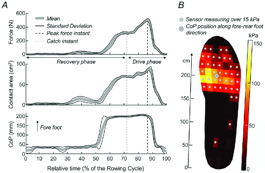
Figure 1: Foot Pressure Map
I measured the driver’s shoe width to be about 110 mm, so I designed the toe cup width to be 120 mm. Using the pressure map, I scaled the width of the force to be 100 mm, and I scaled the force to sum to 800 N, the braking force from past experience. I determined that the toe cup should be offset 8.5 mm to put the Centre of Pressure (CoP) directly on the pedal, but because the foot is smaller than the actual cup, I considered a case where the foot was all the way to one side for sizing purposes.
Hand Calculations
Using this loading data, I found the resultant CoP for when the foot was on either side of the cup. This allowed me to find the bending and shear stresses under braking, which allowed me to determine that the sheet metal would have to be 2.9mm thick! This was not ideal, because not only would this be difficult to bend, but it would be wasting material at the flanges since they experience a significantly lower load.
Because of this, I decided to create a stiffener that would sit behind the main face of the toe cups to take the majority of the load. This would be easier to manufacture since the thickness would no longer be limited by bending, and there wouldn’t be material wasted at the flanges. I found that a 15x7.5 mm stiffener would be sufficient, assuming that the stiffener supported the entirety of the load. I chose to go thicker rather than wider since thickness is more effective at resisting bending than width, so we could use less material and get a lighter pedal by making it thicker. However, I quickly realized that this would create an ergonomics problem, since the contact surface of the pedals would be moving rearwards almost 8 mm. There is a requirement in Formula SAE that the pedal face must be a certain distance from the seat according to a driver template, which our car was already pretty close to failing. For this reason, I increased the width to 50 mm, which allowed the thickness to be reduced to 4.0 mm.
The throttle pedal is a bit thinner and it only experiences 500 N, but otherwise it is identical to the brake. Using hand calculations, I determined that a width of 40 mm would require a thickness of 3.6 mm to support the entire load.
One thing I wasn’t sure of was how the load would be shared between the stiffener and the toe cup itself. So once I had done the initial sizing by hand, I decided to turn to FEA to fine tune everything.
Mechanical APDL
ANSYS Parametric Design Language (APDL) is a set of commands used to control input and output for the ANSYS solver. Using commands instead of the Graphics User Interface (GUI) is advantageous because models can be stored, compared, and built using text files that contain the commands used for the analysis, and it is significantly more flexible.
I decided to use shell elements for the model, which meant I would only have to define the areas, and then I could assign a thickness to each section of the model. For my boundary conditions, I fixed only the Z direction of the stiffener where it would be contacting the pedal (Figure 3). The stiffener and the toe cup were modelled as two separate bodies, and then I coupled the contacting nodes in only the Z direction (Figure 2). The reason I did this was so that the two parts could slide against one another as they deflected, and there would be no transverse shear effects between them, since they would not be glued together in any way in real life.
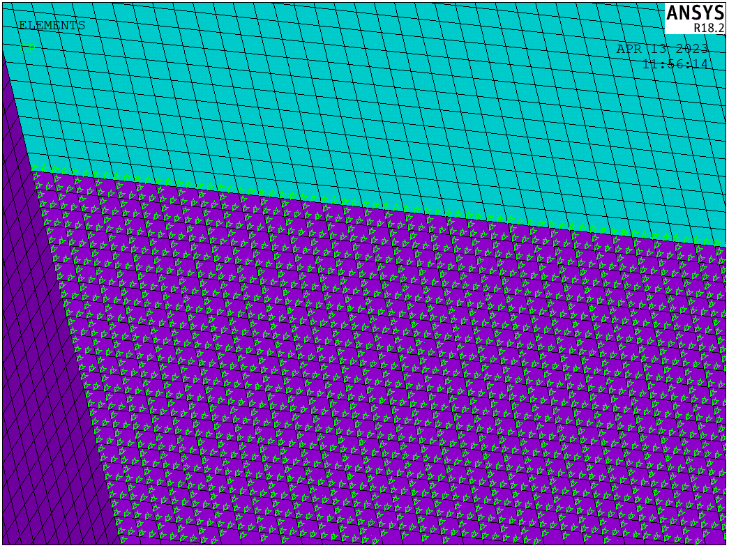
Figure 2: Node Coupling
The real advantage of using APDL is that I was able to create an array that held the force distribution across the face of the pedal, then use a loop to apply the distribution across the entire face (Figure 3). For this study, I assumed that the force was evenly distributed vertically, since the location of the force vertically would not affect the results significantly.
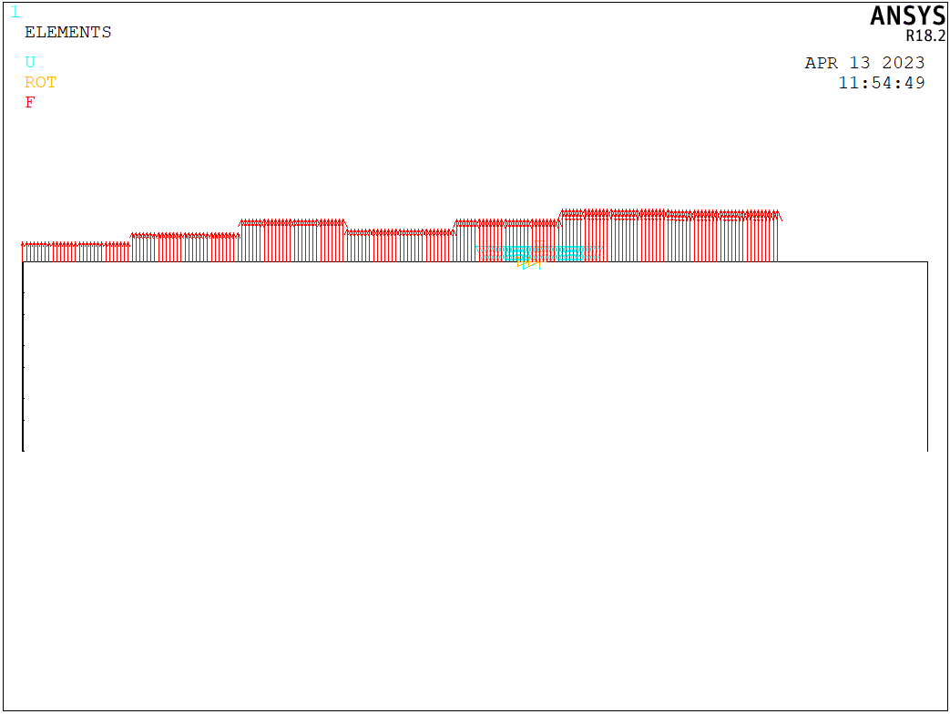
Figure 3: Foot Force Distribution (small foot, offset)
I discovered that 1.2mm was the most common thickness of Aluminum 6061 that we had in stock, so I used this thickness in the model. I found that this thickness barely supported any load, so I wasn’t able to reduce the stiffener size for the brake pedal (Figures 4-6). But since the throttle pedal experiences a smaller load, the sheet metal thickness had more of an effect and I was able to reduce the thickness to 3.0 mm.
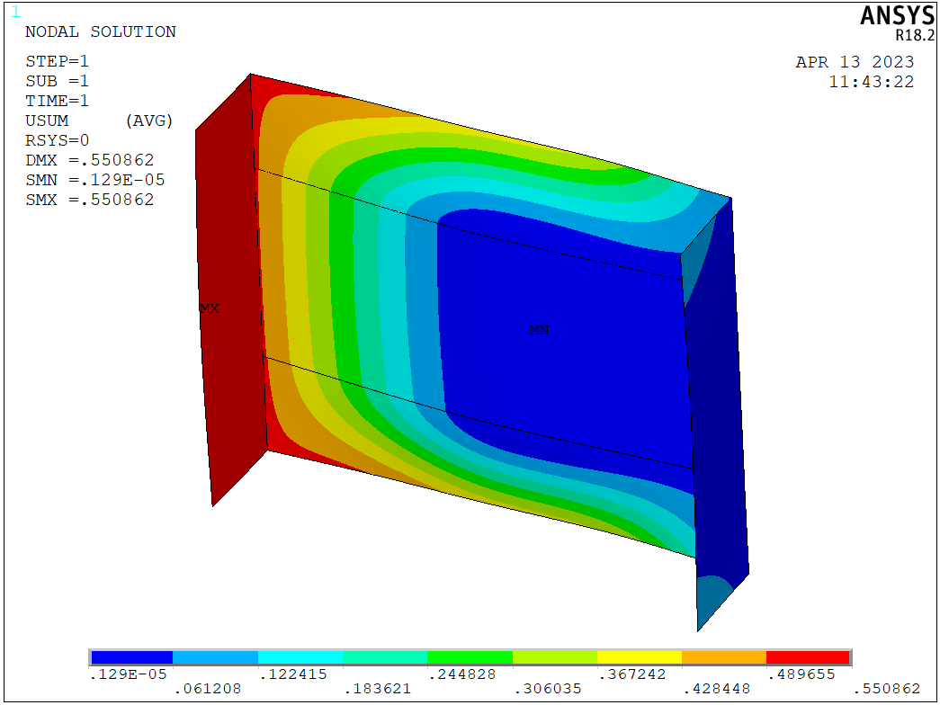
Figure 4: Brake Toe Cup Displacement

Figure 5: Von Mises Stress in the Brake Toe Cup's Face
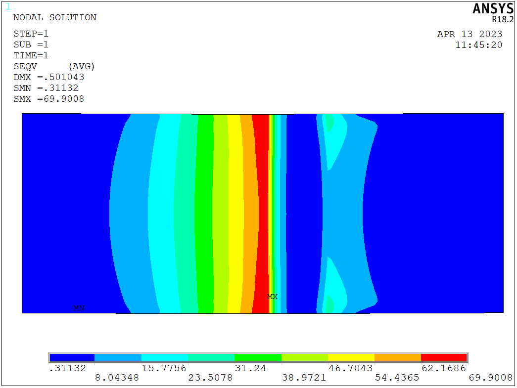
Figure 6: Von Mises Stress in the Brake Toe Cup's Stiffener
Manufacturing
Manufacturing this was fairly easy since there were no complex shapes in the design. The toe cups were made by using the vertical bandsaw to cut the 1.2 mm Aluminum 6061, and then bending them into shape on the brake. The stiffeners were made by milling down 1/4" plate and 1/8” plate for the brake and throttle stiffeners, respectively (Figure 7).
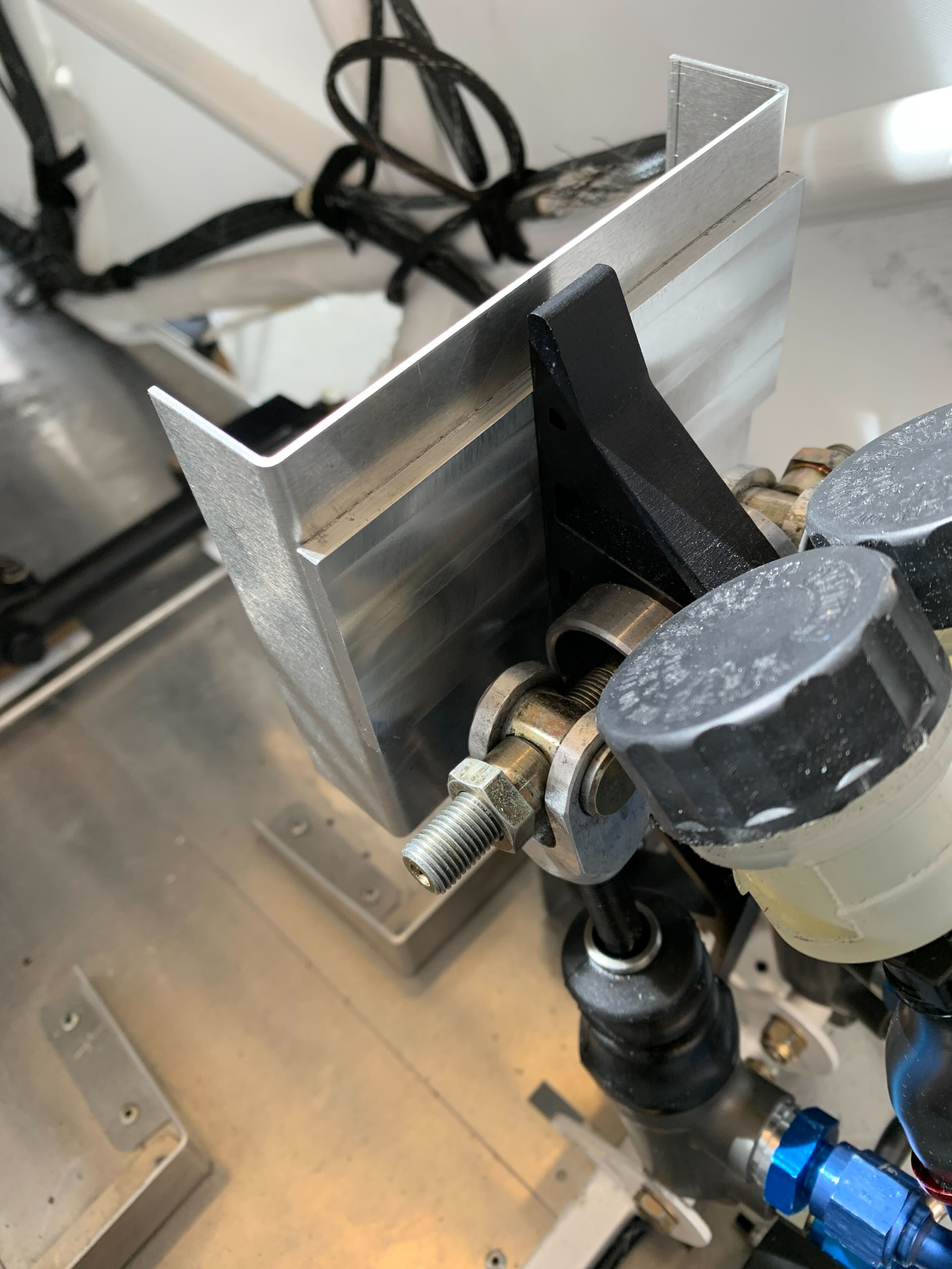
Figure 7: Installed Brake Toe Cup
Unfortunately, we missed the first test, but we were able to test the brake toe cups during our second session. I wanted to test the brakes first since they experience the higher loading, and I was happy to see that there was no deflection! The drivers said that the stiffness was great, and their only complaint was that the flange length was too short, which was an easy fix. We installed the throttle pedal toe cup a few days later, and we saw good results with that one too.
I am pretty confident in this design, so I don’t expect to see it fail during service anytime soon. I used a safety factor of 2, and somewhat conservative design loading, which means I could probably reduce the thickness if I wanted to risk it. And given that the pedal is significantly stiffer and stronger than the toe cup, I expect that even in the event of a toe cup failure, the drivers will still be able to use the pedals effectively.
Conclusion
I’m pretty happy with the way this project went, since I was able to identify a few different possible pitfalls before we ran into them during manufacturing. I learned how to use APDL during my co-op term at BWXT, and I was excited to use my new skills to take on this project. Adding stiffeners was a great idea for manufacturability, but also for mass saving since it was 17% and 16.5% lighter for the brake pedal and throttle pedal, respectively. The combined weight of the toe cups is about 230 g, which is a decent percentage of the braking system so I hope it’s worth it for those drivers! If I had more time, I think I would investigate an “X” pattern stiffener so that the top and bottom of the cups could be better supported, and the thickness could potentially be decreased due to the lower moment arms at the top and bottom. Additionally, a pattern like this could be easily water-jet before milling down the thickness, so it wouldn’t be too hard to make with a bit of planning. Maybe something to look into for next season!