Background
Starting in September 2023, I worked for Tesla for 1 year on the interiors engineering team. This is one of the larger engineering teams since they design everything inside the cabin except for the seats. The interiors team is divided into six subsystems per vehicle:
- Instrument Panel
- Center Console
- Overhead Trim
- Door Trim
- Hard Trim (A, B, C pillars, and liftgate)
- Soft Trim (carpets and flooring)
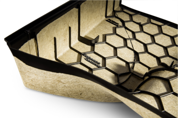
I worked on hard trim for two different vehicles, which is typically a grained mold-in-colour part, or a stiff substrate wrapped with foam and soft materials. Hard trim is usually a well-constrained design, as the goal is to cover functional components such as body and harnesses with soft-touch and aesthetically pleasing panels.
Note that all of the work I did was confidential, so I will be describing my projects very generally using only knowledge and images available to the general public.
General Design Process
The first step to design is to create criteria in 3D CAD which will tell the studio designers the requirements for the trim panel. This will include what to cover, minimum radii, minimum thicknesses, and ergonomic keep-out zones, for example. Then the studio designers will send back a surface which I can thicken to create my part. From there I can determine a first draft of attachment points to the body and other trim panels. This design will then be sent to the CAE team so that they can simulate head impact tests, as well as airbag deployments. There are regulations that limit the maximum acceleration a head can experience, called the head injury criterion, which means that the trim must be able to deflect strikes or crumple to absorb energy. During airbag deployments, the trim must not fracture or detach, or inhibit the deployment. These are the main inputs to the design, and this whole process will go through many iterations as requirements affect one another, parts move, and results come back.
Trim Mass Reduction
The first major project that I did was investigate methods to reduce substrate mass, and I achieved this by using a hybrid-molding process. Typically, trims are either injection molded or compression molded. Injection molding is when melted plastic is injected into a mold, and it cools to take the shape of the part before it is ejected from the mold. Compression molding is when a flat sheet (usually fibrous and/or composite) is inserted into a mold, and the mold clamps down on the sheet, heating it and compressing in into the shape of the part. When the sheet cools it is removed and it retains the shape of the mold.
The advantage of compression molding is that it produces parts with better strength-to-weight ratios thanks to the fibers, but they cannot have complex geometry like ribs or clips. One way to fix this, is to add a second step where the compression formed part is moved into a different mold which injects plastic onto the backside of the part. The melted plastic adheres to the original part as it cools, creating the new features. This is back-injection. However this process is extremely slow.
With hybrid-molding, these two steps are combined into one more expensive tool, which cuts down on the cycle time significantly. Using this process, and optimizing back side features for this process, I was able to achieve massive weight reductions, up to 40%, compared to a conventional injection molded trim.
Interface Design
A somewhat overlooked but important measure of quality is how well parts fit together. Even though interfaces are not usually scrutinized by consumers, large gaps and poor flushness will reduce the perceived quality of the vehicle. The best way to ensure that an interface will look nice is to include part-to-part attachments close to the interface, however this cannot be used everywhere because of variation. The amount of expected variation will mostly depend on part tolerances, body tolerances, attachment and locator placements. Somewhere within the system, parts must be able to move relative to one another to absorb variation, otherwise you are a assuming a perfect vehicle, so one or more trims will be impossible to install. There are two main types of interfaces:
- Butt joint: Needs to be well-controlled to avoid opening gaps or reducing flushness.
- Slip joint: More forgiving to variation but requires an obvious step.
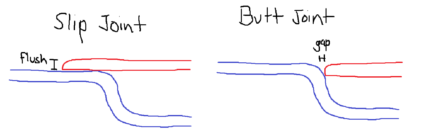
The butt joint will look best when it is well-controlled (i.e. part-to-part locators and attachments are used), because low gap and flushness can be achieved, so it is used in highly visible areas. The slip joint can absorb large variations without opening gaps, but it comes at the cost of a fixed step, so it is used in low visibility areas.
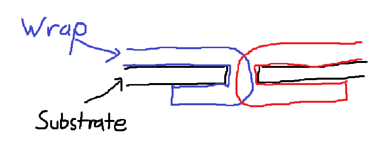
For wrapped trims, the squishiness of the wrap can be exploited to absorb variation when it crushes down. In butt joints, this can allow for some variation in the interface, without sacrificing quality by opening gaps. Trims are designed with nominal interference, so that the wraps crush when installed in reality. In vehicles with many wrapped parts, slip joints can be eliminated entirely since wrap crush can do the job of variation absorption.
By working with the dimensional team to improve part tolerances, as well as using these concepts, I was able to optimize all the interfaces between my trims, to ensure I was achieving the best quality while allowing reasonable variation.
Steering Column Bracket Design
While I was at Tesla, a static vehicle buck was being built to visually evaluate the interior and exterior. Along with my regular part responsibilities, I decided to take on the challenge of building the steering column bracket as well. This needed to be a highly stiff design since the steering was functional, but mass was irrelevant since the car had no drivetrain. So, I opted for a steel design that could be water-jet and bent for ease of manufacturing. This beam also was used to support the instrument panel and display, but the loads from those components were very low, so all I had to do was provide the appropriate mounting points. This is an example which is similar to what I designed, sometimes called a cross-car beam assembly:
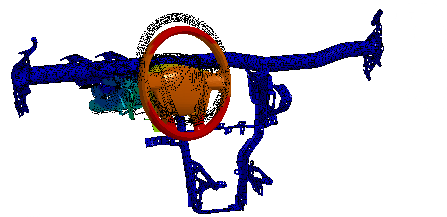
I started by analyzing the loads I expected the design to endure. I found my maximum load by assuming that a 220 lb person was hanging off the edge of the steering wheel. This puts a large torsional moment and downward force on the beam since the steering wheel is cantilevered. I also set a target where the maximum deflection at any point on the beam had to be less than 5 mm, to ensure that the IP doesn't deflect noticeably when using the steering wheel. Using classic force analysis, I determined the expected loads at every critical location, allowing me to spec bolted joints and tube size/thickness by hand. I used Catia V5 FEA to determine the sheet metal thicknesses for the bracket, since the loading is more complex in these areas. The main load-bearing features were the wall flanges (to reduce bending), and the gussets (to reduce twist), so I used the study to optimize these areas the most.
Once the design was complete, I sent off the drawings to be manufactured, and everything was perfect when I received the parts. After installing everything, I hung off the edge of the steering column in its maximum extension position, and had a team-member measure the deflection. I was very happy to hear that the deflection was 4 mm, which was double what I had calculated (2 mm), but still within the target thanks to my factor of safety!
This was a really fun project for me since I had a lot of design freedom, I was able to use my technical abilities in the design, I was able to complete everything within a relatively short time frame, and I was able to see it through and achieve my targets. It was a really nice break from the longer, more constrained projects that I was working on throughout the rest of my internship.
Reflection
This was my longest co-op - originally it was meant to be 4 months but I ended up extending it to 1 year! The reason that I extended is because I really liked my team, the projects that I was working on, and the freedom that Tesla allows their employees. I found that Tesla allows students to approach problems and explore solutions very liberally, compared to some of my previous co-ops which were more restrictive in what work I could do, and how I should do my work. I think this strategy can lead to inefficiencies and overworking, but it also produces more innovative results. It's also a fantastic opportunity to learn and grow your engineering skills, which I took full advantage of by asking for new and different projects whenever the opportunity arose. Personally I was able to find a good work-life balance so I still was able to enjoy California while I was there!
The main reason why I didn't return for my next internship is that I want to vary my co-op experiences as much as possible - this has allowed me to develop a broader skill set and also determine what types of work I enjoy. Tesla was definitely my favorite so far though!
Note that NO images in this post are from my work at Tesla, these are ALL publicly available online.